25+ direct fm transmitter block diagram explanation
Here you can understand the block diagram explanation of the FM TRANSMITTER. The exciter section contains the carrier.
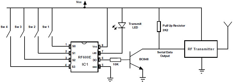
Fm Remote Encoder And Fm Decoder Using The Ics Rf600e And Rf600d
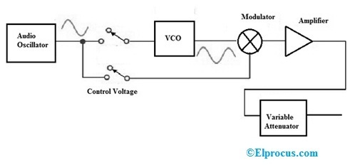
The adder allows modulating signal to be superimposed upon the VCO control voltage thus frequency modulating the circuit.
. The power amplification of the radio signal is carried out in the final stage of the block diagram. For this a device called. Difference between curd and cheese.
1 Answer to Draw a block. The FM transmitter has three basic sections. Using Reactance modulator direct method.
The block diagram of AM transmitter is shown in the. The FM transmitter has three basic sections. Using Reactance modulator direct method.
Excel compare 2 columns and return differences. And in best case scenario it might even reach 10km approximately. It is generalised for AM and FM types of modulation and.
Phone tap detector app iphone. You can use 3v to 12v DC power supply for this circuit. In direct FM generation the instantaneous frequency of the carrier is changed directly in proportion with the message signal.
The part of the Armstrong FM transmitter Armstrong phase modulator which is expressed in dotted lines describes the principle of operation of an Armstrong phase. It makes the signal stronger so that it can be transmitted into the aerial. FM and SSB reception.
Block diagram of direct method of fm generation. FM transmitter FM Transmitter Block Diagram Direct Method. The radio transmitter works block diagram of a simple AM amplitude modulated signal transmitter is shown on Pic22.
Its okay imagine dragons piano. For those who want to make the PCB it is time to get the. FM receiver circuit using transistors.
Radio Transmitter Block Diagram. This block diagram of a radio transmitter in a communication system is very simple and basic. The oscillator does not change frequency as is the case of direct FM.
Many receivers have provision for the reception of FM either the narrow band FM used by mobile networks or the high-quality broadcast transmissions in the 88- to 108. Block diagram of direct method of fm generation. If f osc 10000 MHz R 200 and N 1978.
These points out the major advantage of phase modulation PM or indirect FM over direct FM. Block diagram of FM transmitter and receiver and its explanation. AM transmitter takes the audio signal as an input and delivers amplitude modulated wave to the antenna as an output to be transmitted.
That is the phase. Transmitted Receiver Block Diagrams 25 Marks You need to explain in these two sub-sections the Transmitter Receiver block diagrams in details you should not copy the material from.
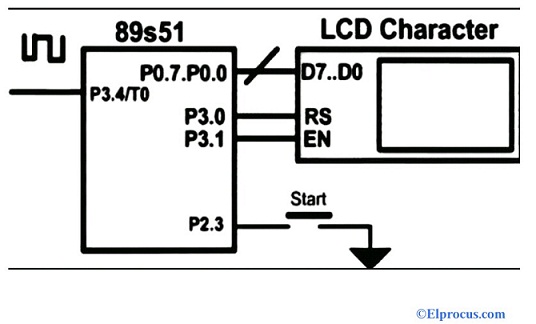
Frequency Counter Block Diagram Circuit Types And Its Applications
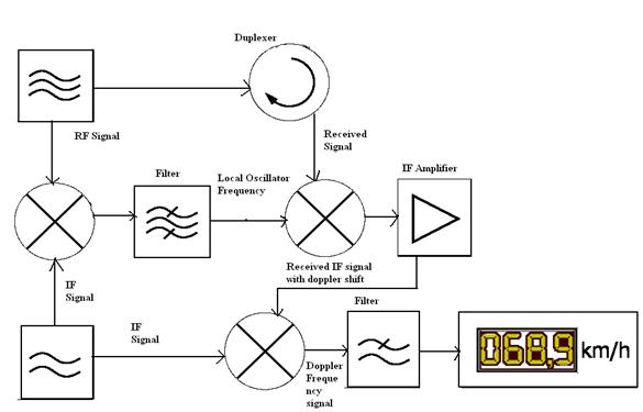
Radar Basics Types Working Range Equation Its Applications
2

Transmitter Receiver An Overview Sciencedirect Topics

Fm Wireless Microphone Circuit Diagram Eleccircuit Com Circuit Diagram Electrical Circuit Diagram Circuit

Rf Receiver Schematic Diagram Wireless Remote Control Remote

The Interceptor Aims To Fix Vulnerability In Millions Of Alarm Systems
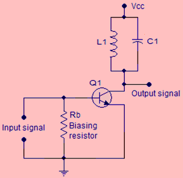
Know All About Class C Power Amplifier Circuit And Tutorial

The Interceptor Aims To Fix Vulnerability In Millions Of Alarm Systems
2

Simple Fm Receiver With Ear Phones What Is Electronics Fm Radio Receiver Receiver Electronic Circuit Projects

Fm Modulation System Fm Transmitters Communication System System
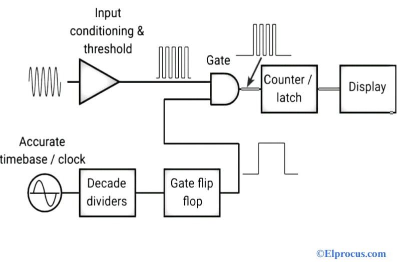
Frequency Counter Block Diagram Circuit Types And Its Applications

Transmitter Receiver An Overview Sciencedirect Topics

Low Power Mw Am Transmitter R Electronics

50 Tips N Tricks For Nautel S 50th Nautel Support
Signal Generator Circuit Working Types And Its Applications